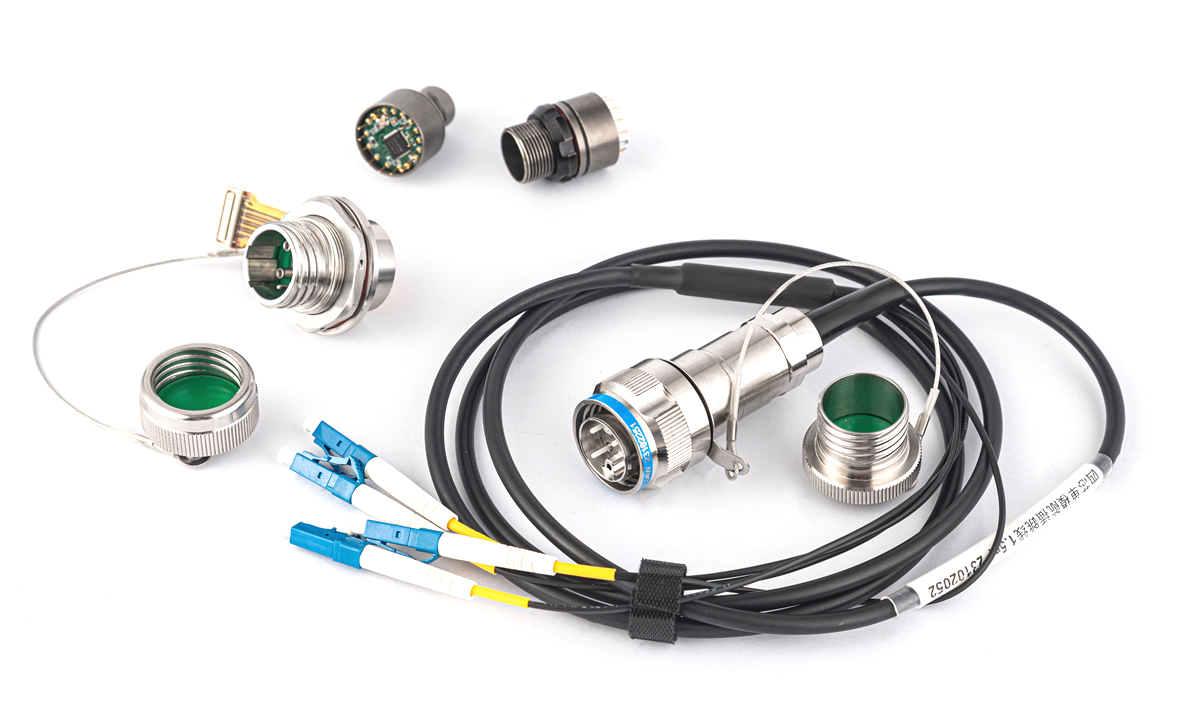
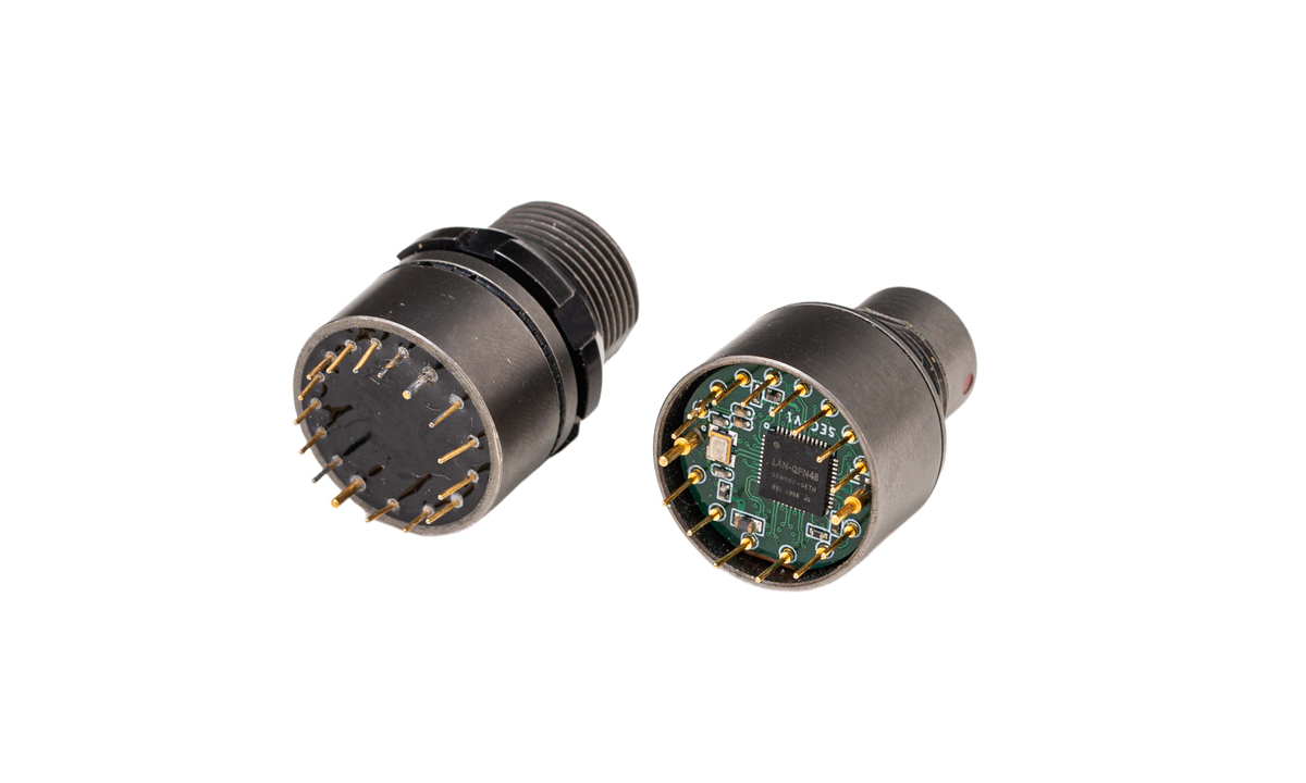
The Dragon Structure is an advanced optical module design system independently developed by Gigac Technology. It integrates the latest photoelectric conversion technology, precision manufacturing processes, and efficient heat dissipation management solutions to ensure that the optical module can maintain stable performance output even in extreme environments. This architecture fully considers the heat dissipation, electromagnetic compatibility, and environmental adaptability of the optical module from the beginning of its design, providing a solid foundation for the stable operation of the optical module. Gigac Technology patented product (Patent No.: ZL 2023 2 2383952.3)
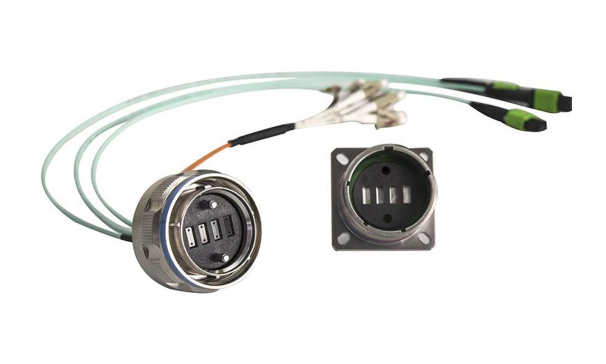
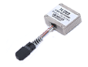
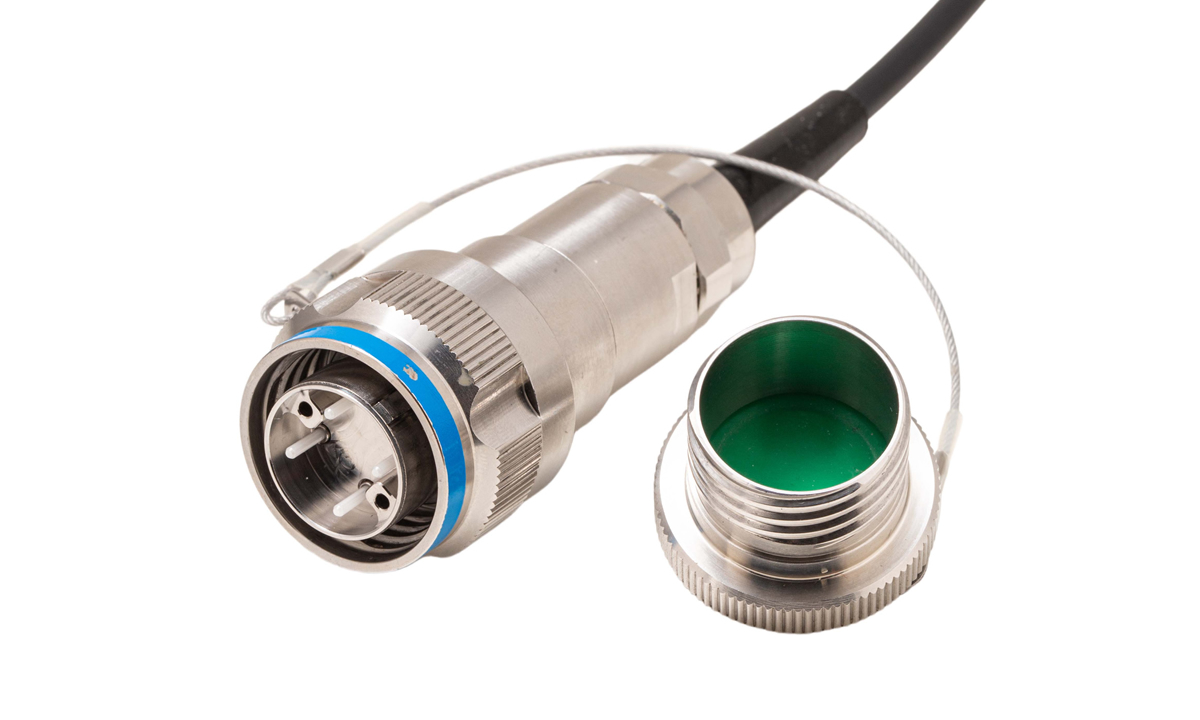
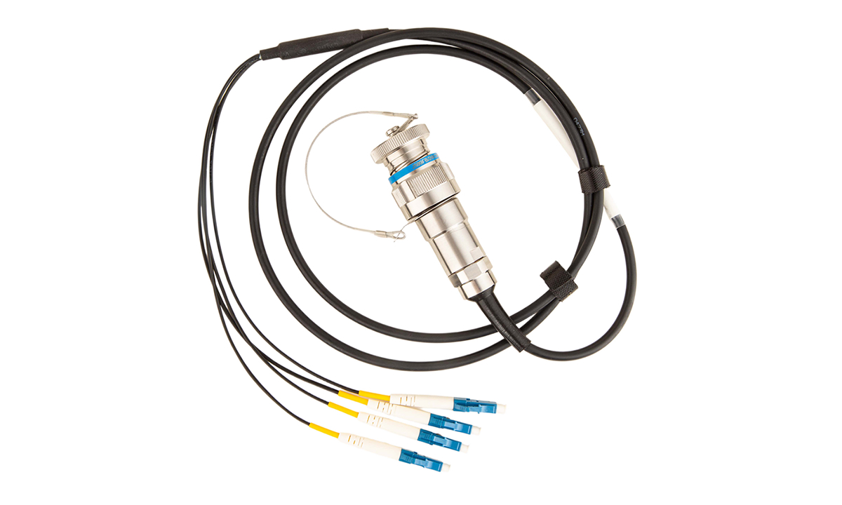
The Dragon Structure's integrated structure eliminates fiber optic patch cords. This eliminates internal fiber interconnects, reducing design complexity, optimizing internal processes, and improving transmission reliability. Optical signals are transmitted directly from the optical module through internal optical adapters to the aviation plug-in interface, reducing intermediate connections and avoiding the loss and instability caused by plugging and unplugging fiber optic patch cords. This saves 30% to 50% of internal space compared to traditional solutions. Furthermore, this design provides a relatively stable internal optical path, reducing the risk of optical signal interruption or interference due to external vibration and impact, making it more adaptable to complex and harsh operating environments.
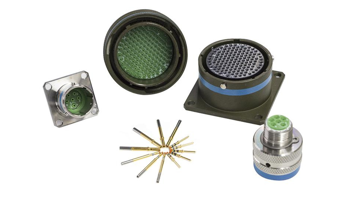
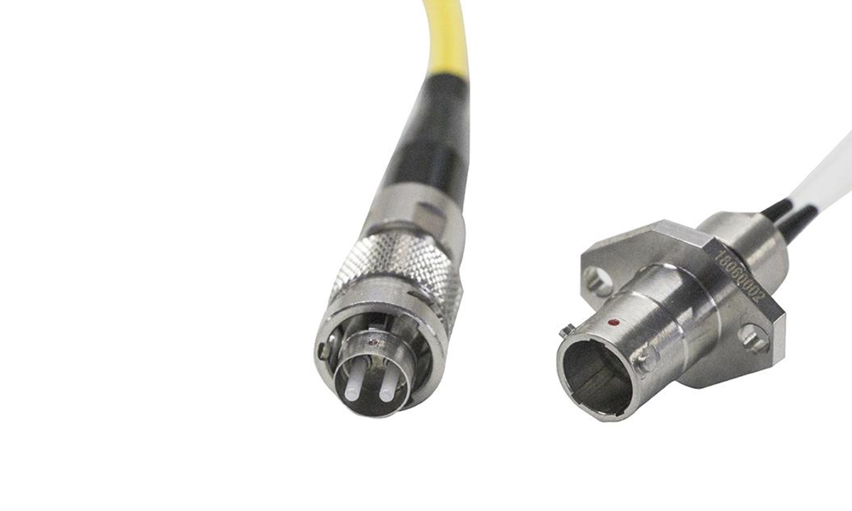
Conventional optical module usage in military equipment:
1. In military equipment, due to the sealed chassis, the equipment panel requires the use of FC or GJB599 series optical connectors. At least one optical connector connection is required from the optical module to the equipment panel connector. The loss on one end is 0.5-1.5dBm, and the loss on both ends is 1-3dBm, shortening the transmission distance to 2-6km.
2. In a standard plug-in board chassis (such as VPX, CPCI, or other custom standard chassis), if the optical connector is located at the rear of the device and the optical-to-electrical converter module is located on the front plug-in unit board, an optical backplane connector may be added for serviceability. This design results in three optical interconnects within the device (see ①, ②, and ③ in the figure below). Each end results in a loss of 1.5-4.5dBm, resulting in a loss of 3-9km in transmission distance. This loss is quite significant. Therefore, it is necessary to optimize the internal optical-to-electrical converter design to reduce the severe loss caused by excessive internal optical connector interconnections.

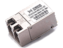
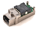
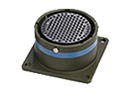
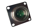
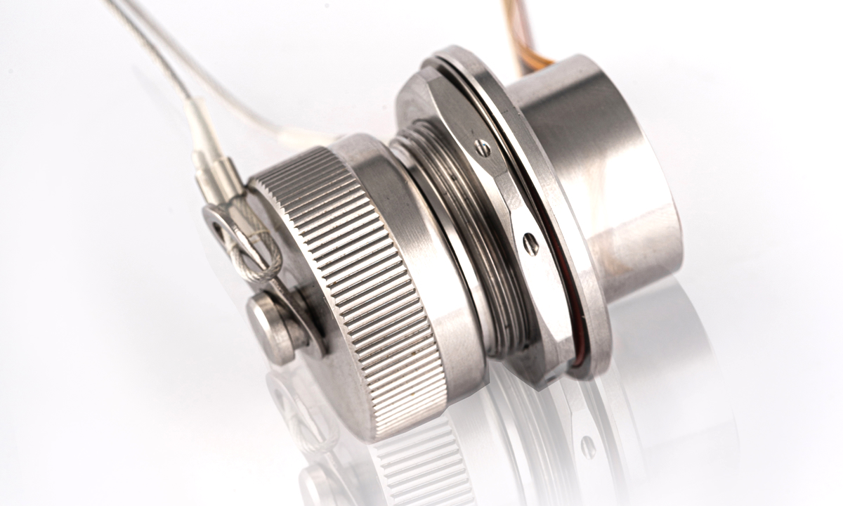
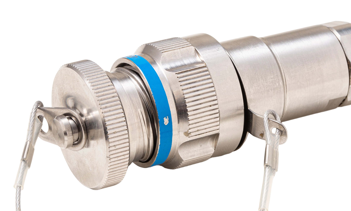
What is an aerial plug-in (Dragon Structure) optical module?
This is the most reliable optical module ever invented:
Ultra-high vibration resistance—easily meets missile-grade requirements;
Ultra-high sealing—easily achieves airtightness, watertightness, and oiltightness;
Ultra-high operating temperature—easily increases operating temperature by over 10°C;
Ultra-high electrostatic performance—easily maintains level 4 electrostatic adaptability;
Ultra-low power consumption—easily reduces power consumption by over 10%;
Extremely few transition points—easily reduces link attenuation by over 1dBm
This optical module significantly reduces costs for customers:
Ultra-high integration—easily saves over 5 square centimeters of board space;
Ultra-high heat dissipation—easily reduces module cooling costs;
Ultra-simple design—easily saves fiber routing space and costs.
Introduction to the Use of Plug-in (Dragon Structure) Optical Modules (Patent No.: ZL 2023-2-2383952.3)
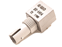
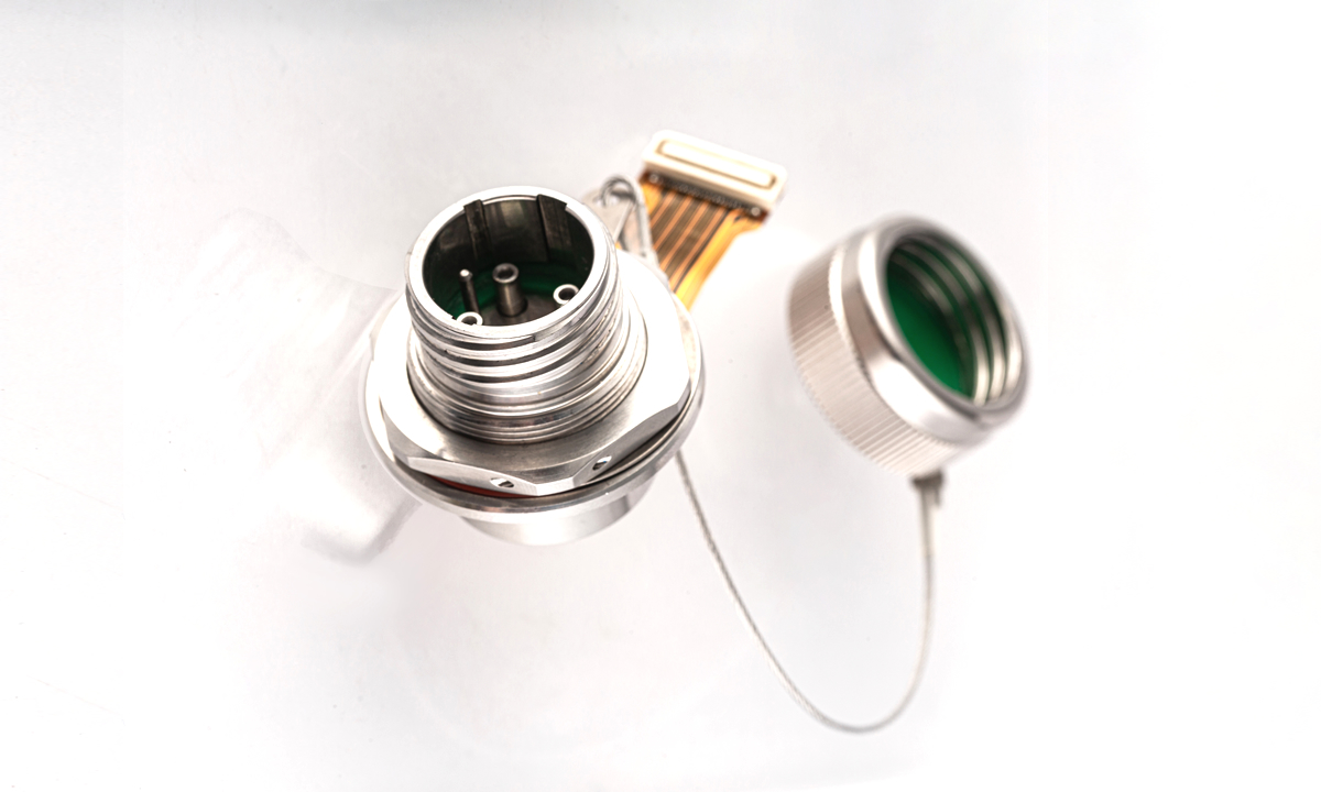
Installation Method:
1. Directly mount on the chassis or panel;
2. Electrical Connection Method:
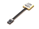
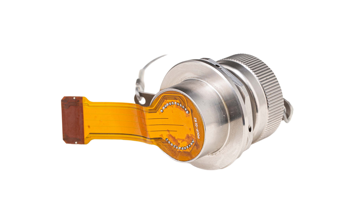
a. Direct soldering via pins or soldering via a flexible printed circuit board;
b. Direct snap-on connection via a flexible PCB and micro-rectangular connector.
Dragon Structure optimizes internal optical-to-electrical conversion solutions:

As shown in the figure above, this design achieves the same performance as civilian equipment, eliminating internal fiber interconnects. This reduces internal design complexity, optimizes internal processes, improves transmission reliability, and extends the fiber transmission distance of the equipment.
Solutions for saving internal equipment and PCB space:
Compared to traditional solutions, this solution saves 30% to 50% of internal space, which is very beneficial for miniaturized devices and improves reliability. Because the module is mounted directly on the chassis, no additional heat dissipation design is required.
Application Scenarios for Aerial Plug-in ( Dragon Structure ) Optical Transceiver Modules
High-Density Layout Scenarios
High-Vibration Environment Scenarios
Challenging Heat Dissipation Design Scenarios
Related Experimental Reports
Vibration Test Results
| Test Items | Test Conditions |
| Mechanical Vibration Test | Vibration: Frequency: 20Hz~2000Hz-20Hz; 20Hz~80.8Hz: Displacement: 1.52mm; 80.8Hz~2000Hz: Speed: 20g; Sweep Time: 4min/cycle; Number of Cycles: 4/direction; Sweep Directions: X, Y, and Z. |
Shock Test Report::
| Test Items | Test Conditions |
| Shock Test | The shock load is 15 times. 5 times in each of three directions. Half-sine wave, 500g, 1ms. (Refer to GJB548B) |
Centrifugal acceleration experiment test report:
| Test Items | Test Conditions |
| Centrifugal Acceleration Test | Y1 Direction, 2000g/min |
Centrifugal Acceleration Test Report::
| Test Items | Test Conditions |
| Salt Spray Test | Temperature: 15-30°C Relative Humidity: 20%-80% Air Pressure: 73kPa-106kPa Test conducted according to the test method in GJB 150.11A-2009. Test Conditions: 1: Unmated plugs, receptacles, and connectors. 2: 24-hour salt spray exposure and 24-hour drying cycle (excluding optical wiring boxes), typically 500 hours. |