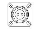
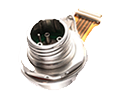
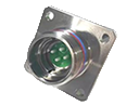
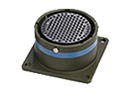
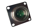
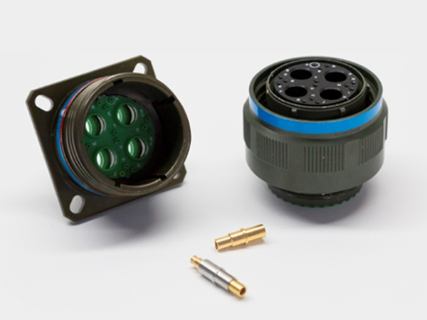
The J599III series high- and low-frequency hybrid connectors produced by Xinrui Technology are high-performance connectivity products. They feature a rugged housing with excellent mechanical properties, resisting shock and vibration. Their compact internal structure enables low-loss, high-bandwidth transmission at high frequencies, as well as stable conductivity at low frequencies. They offer high data rates and low contact resistance, meeting diverse signal transmission requirements. Furthermore, they offer excellent electromagnetic shielding capabilities, making them suitable for use in complex electromagnetic environments. Widely used in aerospace, military equipment, communications, industrial automation, and other fields, they provide reliable connectivity for stable operation of various devices under harsh conditions and are essential components in modern electronic systems.
Product Features
Comply with the GJB599B (MIL-DTL-38999M) III series standard
Triple-start thread for quick connection with anti-loosening structure
Five-key circumferential identification and positioning for blind mating and error-proof insertion
Outer shell available in different materials and coatings to adapt to various environmental requirements
Equipped with electromagnetic shielding function
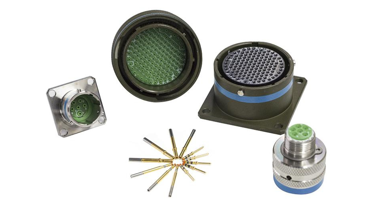
Compact size, lightweight, and high contact density
Suitable for use in complex environments with strong vibrations, rain, windblown sand, and humidity
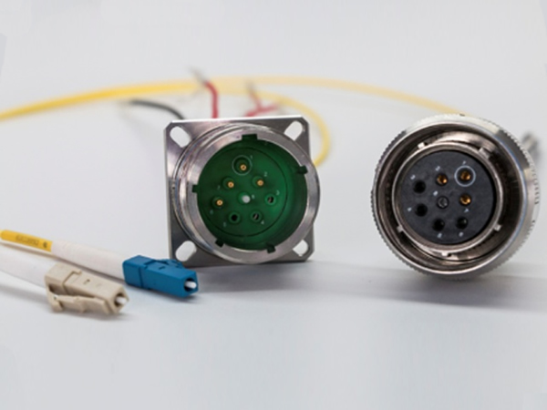
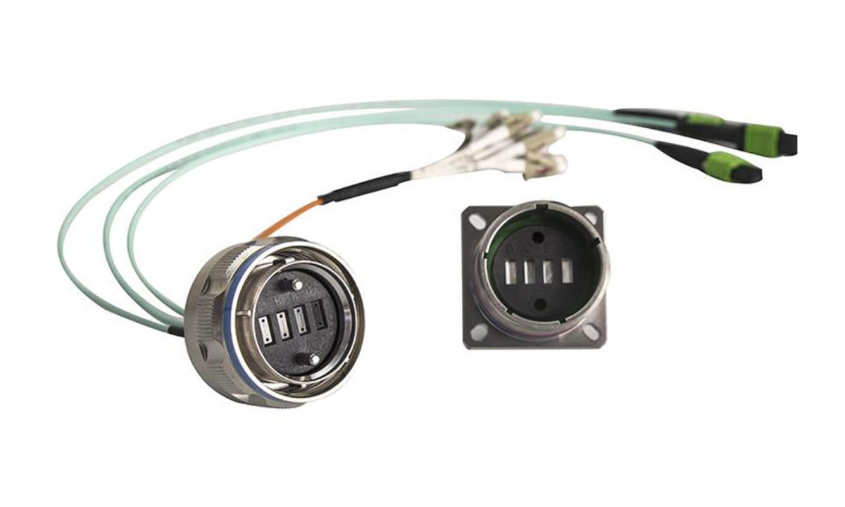
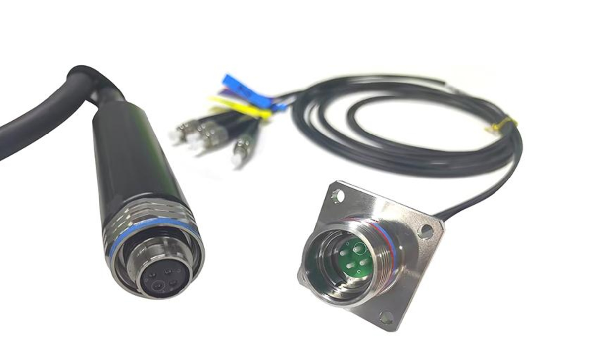
Capable of mixed mounting of power, high-speed, high-frequency, and optical contacts
Integrated connection of microwave signals, high-speed data, optical fibers, and power control signals
Mechanical Performance
• Mechanical Life:
500 cycles of insertion and extraction
• Shock:
3ms half-sine wave with a peak acceleration of 300G
• Vibration:
Sine: 60G with temperature cycling and simulated conditions (36 hours)
Random: 44.1grms at high temperature
49.5grms at ambient temperature
Environmental Performance
• Temperature Range:
Class K, F: -65°C to +200°C
Class W, MW: -65°C to +175°C
• Sealing:
Mating connectors comply with the low-pressure immersion requirements of MIL-DTL-38999M
• Salt Spray:
Class K: 500 hours
Class F: 48 hours
Class W: 500 hours
Class MW: 192 hours (acidic atmosphere)
• Damp Heat:
As per MIL-DTL-38999M: 24 hours, 10 cycles
• Fluid Resistance:
Resistant to various fuels, coolants, and solvents
Electrical Performance
• Voltage Endurance: V
Operating Conditions | Sea Level | 21,000M Altitude |
M | 1300 | 800 |
N | 1000 | 600 |
I | 1800 | 1000 |
II | 2300 | 1000 |
• Insulation Resistance: ≥5000MΩ (at 500V DC)
• Contact Resistance and Rated Current of Contacts:
Contact Specifications | Working Diameter (mm) | Contact Resistance (mΩ) | Rated Current (A) |
22D | Φ0.76 | ≤12 | 5 |
20# | Φ1.00 | ≤5 | 7.5 |
16# | Φ1.60 | ≤2.5 | 13 |
12# | Φ2.40 | ≤1.5 | 23 |
10# | Φ3.15 | ≤1.0 | 40 |
Shielded Contacts
Low-Level Contact Resistance (Applicable to Inner Contacts Only):
Contact Specifications | Initial Value(mΩ) | After Testing(mΩ) |
16# | 170 | 204 |
12# | 55 | 66 |
Contact Resistance (Test Current and Voltage Drop):
Contact Specifications | Contact | Test Current | Voltage Drop max (mV) | |||
25℃ | 175℃ | 200℃ | ||||
Normal Conditions | After Testing | |||||
16# | Inner Contact | 1A | 170 | 204 | 290 | -- |
Outer Contact | 12A | 150 | 180 | 255 | -- | |
12# | Inner Contact | 1A | 170 | 204 | -- | 290 |
Outer Contact | 12A | 150 | 180 | -- | 255 | |
Withstand Voltage (Between Inner and Outer Contacts):
750V RMS (Root Mean Square) at Sea Level
250V RMS at 15,240 meters (approximately 50,000 feet)
12# Coaxial Contact
Nominal Impedance: 50 Ω
Low-Level Contact Resistance (Applicable to Inner Contacts Only):
Initial Value: 55mΩ
After Testing: 66mΩ
Withstand Voltage (Between Inner and Outer Contacts):
1000V RMS at Sea Level
250V RMS at 15,240 meters
Contact Resistance (Test Current and Voltage Drop):
(Specific values, test current, and voltage drop levels need to be determined according to the product design or relevant standards.)
Voltage Standing Wave Ratio (VSWR):
Within the frequency range of 500MHz to 3GHz, the VSWR should not exceed 1.2 + 0.04F, where F is the frequency in GHz, under the following three conditions:
(This specification ensures that signal reflections remain within acceptable limits during transmission through the coaxial contact, thereby maintaining signal transmission efficiency and quality.)