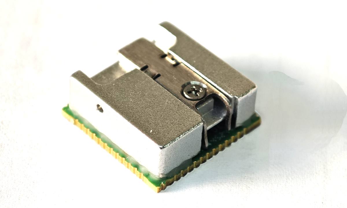
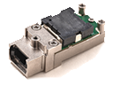
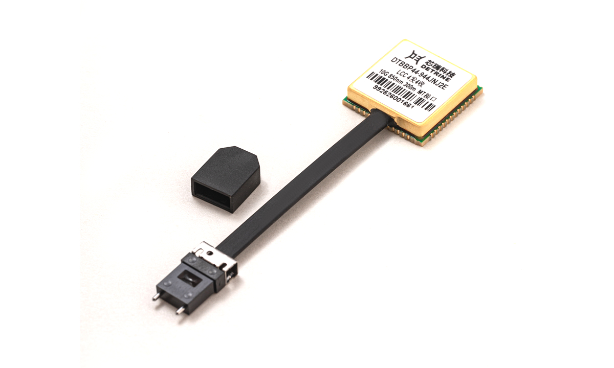
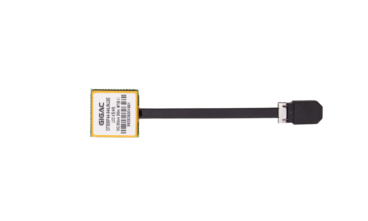

This process seamlessly solders LCC (Leadless Chip Carrier)-packaged optical modules to PCB substrates by precisely controlling the temperature profile, achieving pinless surface mount technology (SMT) and avoiding the problems of cold solder joints and thermal stress concentration associated with traditional manual soldering. The module's packaging materials and structure have been specially optimized to withstand peak temperatures of up to 260°C during the reflow soldering process without damaging the internal optoelectronic components, ensuring consistent and stable mass production. Reflow soldering technology also enables more compact module layouts. Combined with the low-profile nature of the LCC package, it can be adapted to high-density PCB designs, meeting the deployment requirements of space-constrained scenarios such as servers and airborne equipment. Furthermore, this process significantly simplifies the production process, supports fully automated assembly, and reduces manufacturing costs. The solder joints offer high mechanical strength and excellent temperature resistance, ensuring the module's resistance to vibration and thermal fatigue in harsh industrial environments (-55°C to +85°C). This technology is a key enabler for efficient mass production and highly reliable operation of high-speed optical interconnect equipment.
Product Features:
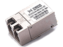
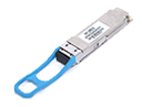
2-channel transmit, 2-channel receive / 4-channel transmit, 4-channel receive, parallel fiber channel
Supports single-channel 10.3125Gbps transmission
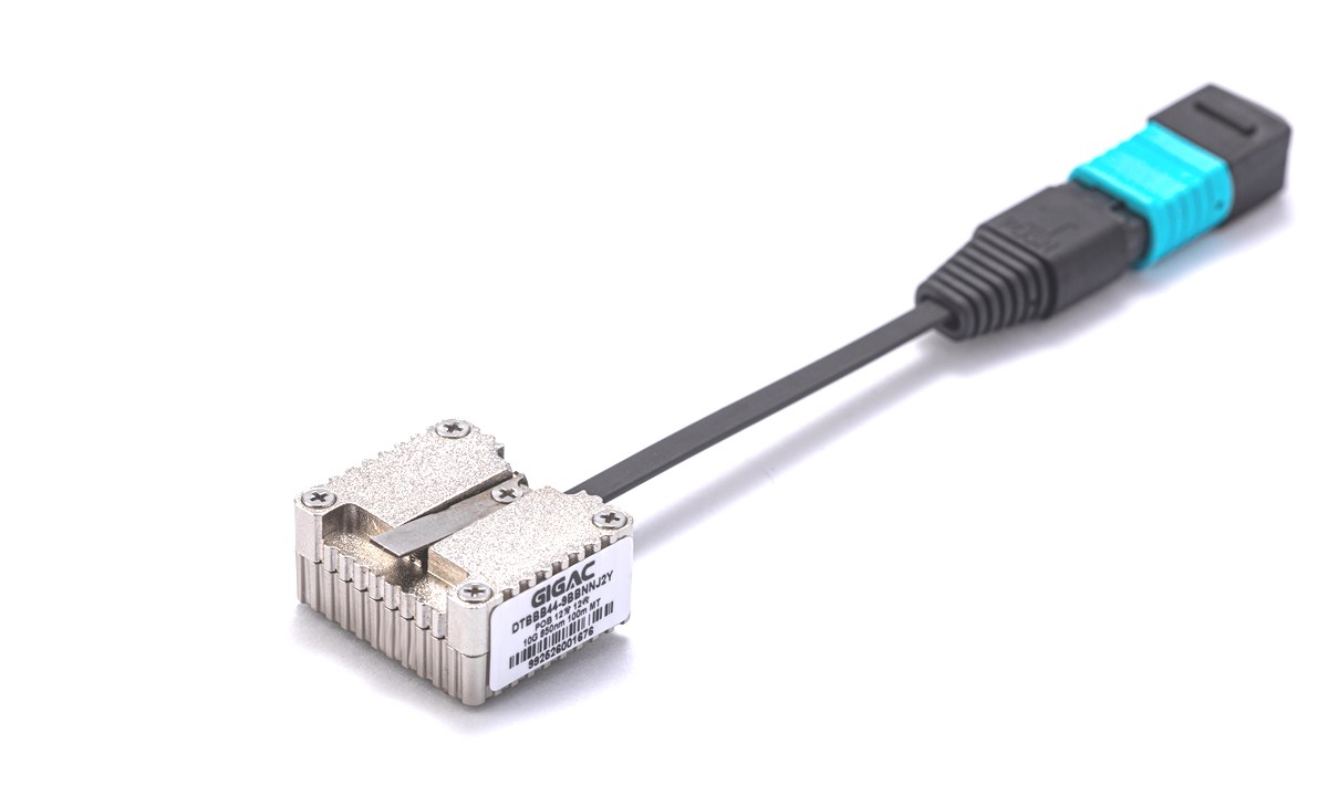
OM3 multimode fiber transmission distance of 100m
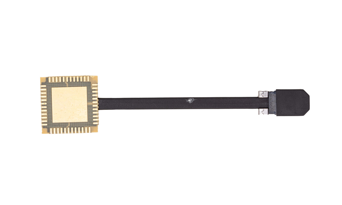
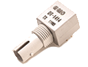
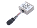
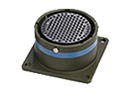
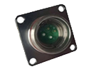
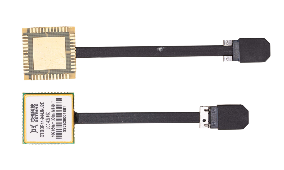
Optional flat fiber, round fiber, loose fiber, spring-loaded, or with guide pins
Single 3.3V power supply
CML level differential data input/output
I2C serial data interface communication and monitoring
Compact design, high density and high capacity
Reflow soldering
Product Grades:
Military Industrial Grade (J): -40°C to +85°C
Military Extended Industrial Grade (M): -55°C to +85°C
Custom Temperature Grade (D)
Applications:
Supports very short-distance high-speed data communication links
Server and storage array interconnection
Airborne radar
Other optical links
Implementation standards:
Compliant with IEC-60825 Class I laser safety standard
ROHS 2.0
Ordering Information:
| Model number | Package | Rate | Wavelength | Distance | Fiber | Interface | Temp(note1) |
| DTBBQ44-922*(note2)NJ2R*(note3) | LCC32 | 10Gbps | 850nm | 100m | MML | MT | -40°C~+85°C |
| DTBBQ44-922*(note2)NM2R*(note3) | LCC32 | 10Gbps | 850nm | 100m | MML | MT | -55°C~+85°C |
| DTBBP44-944*(note2)NJ2R*(note3) | LCC48 | 10Gbps | 850nm | 100m | MML | MT | -40°C~+85°C |
| DTBBP44-944*(note2)NM2R*(note3) | LCC48 | 10Gbps | 850nm | 100m | MML | MT | -55°C~+85°C |
Note 1: Case temperature.
Note 2: "*" = H indicates flat fiber; "*" = J indicates round fiber; "*" = N indicates loose fiber (default with a transparent threaded tube); "*" = P indicates flat fiber with a spring; "*" = Q indicates round fiber with a spring.
Note 3: "*" indicates pigtail length. See the pigtail length code table for details.
Pigtail length code table:
| Pigtail length(mm) | code | Pigtail length(mm) | code |
| 30 | 0 | 150 | R |
| 50 | A | 160 | S |
| 55 | B | 170 | T |
| 60 | C | 180 | U |
| 65 | D | 190 | V |
| 70 | E | 200 | 2 |
| 75 | F | 300 | 3 |
| 80 | G | 400 | 4 |
| 85 | H | 500 | 5 |
| 90 | J | 600 | 6 |
| 95 | K | 700 | 7 |
| 100 | 1 | 800 | 8 |
| 110 | M | 900 | 9 |
| 120 | N | 1000 | L |
| 130 | P | 1500 | Z |
| 140 | Q | custom made | Y |
Note:
For pigtail lengths ≥50mm, flat, round, and loose fibers are available, with options for springs and guide pins.
For pigtail lengths <50mm, flat fibers can be used without springs.
The standard pigtail length tolerance is ±L*5%.
Special requirements will be discussed separately.
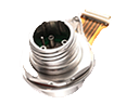
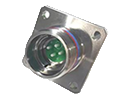
Module Dimensions (in millimeters, tolerance for unspecified items is ±0.2mm)

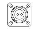
Recommended PCB size

Module Reflow Soldering (This process only supports products that meet the reflow soldering process)
I. Pre-Soldering Preparation
1: Before soldering, it is recommended to clean the soldering pads (clean with ethanol and wait until the ethanol has completely evaporated before soldering).
2: When using reflow soldering, operators are required to wear an anti-static wrist strap, anti-static finger cot, or gloves.
3: When placing the module during reflow soldering, ensure that it is aligned with the silkscreen frame, with an error of no more than 0.1mm.
4: If the module soldering position is close to the board edge, the module body may slightly tilt or become unstable due to the weight of the pigtail. If this occurs, it is recommended to design tooling at the board edge to support the pigtail and ensure that the module body can be completely level. Otherwise, soldering problems may occur, such as poor soldering or even failure to solder.
5: Before reflow soldering, the MT fiber connector must be protected with a dust cap and appropriate insulation material to prevent contamination.
II. Soldering Operation Requirements
1. We recommend using leaded solder paste. The furnace temperature should not exceed 230°C. The temperature inside the furnace should be uniform, with a maximum temperature difference of 10°C at any point. The soldering time is recommended to be ≤ 90 seconds, and the entire reflow process should last ≤ 8 minutes.
Reflow Oven Temperature Curve Reference Chart:
2: The module should be reflowed ≤ 2 times. Reflowing more than 2 times may permanently damage the module's internal design, causing irreversible damage to product performance and potentially leading to product failure.
3: During reflow, ensure the fiber pigtails are free of tin and cannot be pressed by any heavy objects. Protect them with high-temperature-resistant materials.
III. Post-Soldering Inspection and Processing
1: If the fiber pigtails appear bent after reflow and return to room temperature, this is normal. Place the module in an environment between 70°C and 90°C. Once the heat shrink tubing softens, remove it from the high-temperature environment and gently straighten the pigtails. Once the pigtails return to room temperature, they will straighten again.
2: The MT dust caps may become deformed after reflow. This is normal. Please replace them with new ones to protect the MT optical port endfaces.
3: After soldering, verify that there are no short circuits or cold joints in the module solder joints using X-ray or other technical means.
IV. Cleaning and Inspection of Optical Ports Before Testing
1: Before testing the module, the optical port must be cleaned with a dust-free cotton swab dipped in alcohol. To clean the optical port, use a clean, dust-free cotton swab dipped in alcohol and wiping it in one direction, rotating the swab gently. Wipe no more than three times per swab. Allow the alcohol to completely evaporate before plugging or unplugging. Before plugging or unplugging, wipe the optical port connected to the patch cable in the same manner.
2: A fiber end-face inspection instrument is recommended for inspecting the optical fiber.