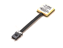
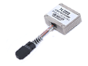
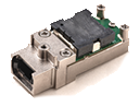
Gigac Technology's Gecko-based LCC optical module is a high-performance, pluggable optical communication module designed for high-speed data communications and optical links. This product series is fully compatible with traditional fixed-fiber pigtail LCC optical modules and is directly interchangeable, providing users with greater flexibility and convenience.
The Gecko-based LCC optical module supports a variety of parallel fiber channel configurations, including 4 transmitters and 4 receivers, 4 transmitters and 4 receivers, and 8 transmitters and 8 receivers, meeting the needs of diverse application scenarios. It supports a wide range of single-channel speeds, from 155M to 25Gbps, making it suitable for a variety of high-speed data transmission scenarios. The module uses OM3 multimode fiber for transmission distances up to 100 meters and offers a variety of pigtail options, including flat, round, and loose fiber. It comes standard with an MT interface and a pluggable design, allowing users to flexibly configure it to meet their needs.
The Gecko-based LCC optical module is widely used in very short-distance high-speed data communications, server and storage array interconnects, airborne radar, and other optical link scenarios. Its design complies with the Class I laser safety standard IEC-60825 and ROHS 2.0 environmental standards, ensuring product safety and reliability. Gigac Technology provides a detailed pigtail assembly guide, allowing users to select different pigtail lengths based on their needs. Customization services are also available to meet diverse application requirements. Whether assembling the pigtails pre-installed or after module installation, the Chihu-architecture LCC optical module provides a simple operation process and reliable connection performance.
Product Features:
Parallel fiber channel support: 4 transmitters and 4 receivers; 4 transmitters and 4 receivers; 8 transmitters and 8 receivers, etc.
Supports single-channel data rates: 155M, 1.25G, 2.5G, 6G, 10G, 16G, 25G, etc.
OM3 multimode fiber transmission distance: 100m
Flat fiber, round fiber, loose fiber, spring-loaded, or with guide pins available
Pluggable optical interface, standard MT interface (pigtails optional)
Single 3.3V power supply
Differential data signal input/output: CML levels
I2C serial data interface for communication and monitoring
Compact design, high density and high capacity
Manual soldering
Product grade:
Military Grade (J): -40°C to +85°C
Military Extended Grade (M): -55°C to +85°C
Applications:
Supports very short-range, high-speed data communication links
Server and storage array interconnects
Airborne radar
Other optical links
Implementation standards:
Complies with Class I laser safety standard IEC-60825
ROHS 2.0

Principle block diagram of four-receive four-transmit LCC optical module
Product Ordering Information Sheet:
| Model | Speed | Wavelength | Transmission distance | Fiber type | Interface | Temperature |
| DTBBT44-944SNJ2 | 10.3125Gbps | 850nm | 100m | 多模 | MT | -40℃~+85℃ |
| DTBBT44-944SNM2 | 10.3125Gbps | 850nm | 100m | 多模 | MT | -55℃~+85℃ |
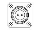
Module size (unit: mm, tolerance is ±0.2mm if not marked)
![1742192736190010[1]](https://gdz.suanmingdashi.com/uploadfile/ueditor/image/202509/17580158442856a6.jpg "1742192736190010[1]")
Gecko Structure LCC Module Pigtail Assembly (Pigtail end interface can be customized, standard is MT interface)
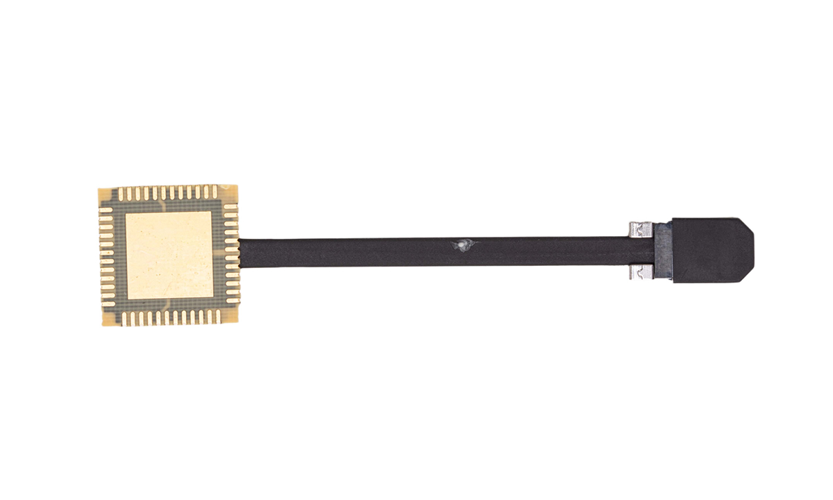
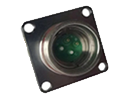
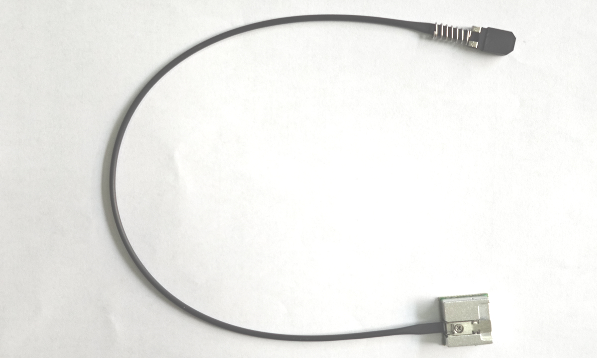
(1) The module pigtail can be assembled after the module body is properly installed, or the pigtail can be assembled in advance and then installed on the mainboard. The pigtail inserted into the module side is a dedicated pluggable 1*12 core jumper, as shown in the yellow part in the figure below.
![1742192978194153[1]](https://gdz.suanmingdashi.com/uploadfile/ueditor/image/202509/17580158891c972e.jpg "1742192978194153[1]")
Module pigtail reference diagram
(2) The recommended assembly sequence is as follows:
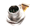
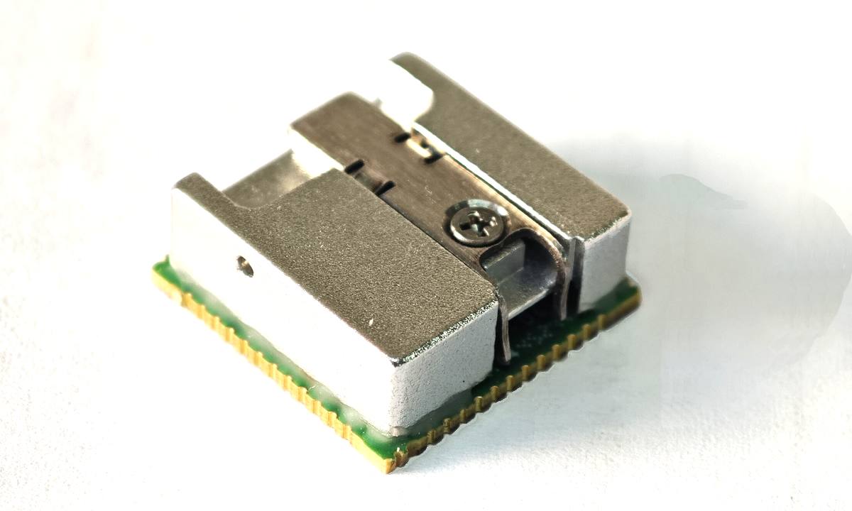
1. Gently press down the spring on the top of the module body, then insert the pigtail. Note that the jumper needs to be inserted in the direction shown in the figure. Refer to the figure below:
![1742193035517409[1]](https://gdz.suanmingdashi.com/uploadfile/ueditor/image/202509/1758015941e02c81.jpg "1742193035517409[1]")
Refer to Figure 1 for pigtail assembly.
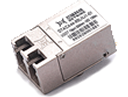
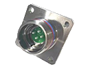
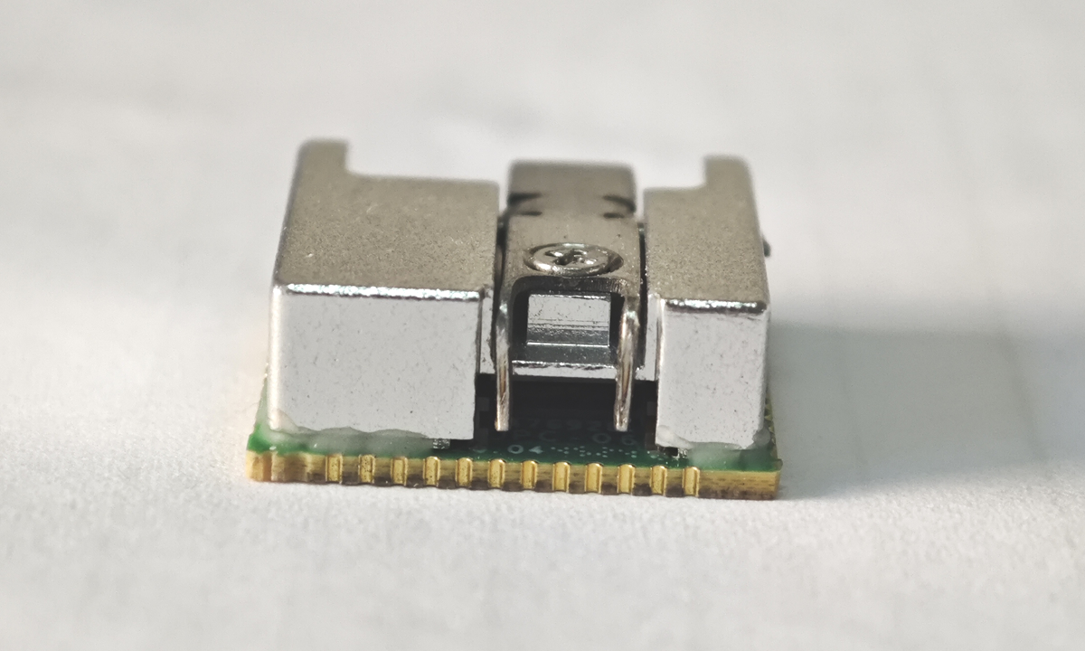
2. After inserting the pigtail, release the top spring clip and inspect the optical port to ensure the spring clip is properly engaged with the pigtail's MT connector. When properly assembled, the spring clips should be approximately engaged with the left and right shoulders of the jumper connector, as shown in the figure below.
![1742193170112036[1]](https://gdz.suanmingdashi.com/uploadfile/ueditor/image/202509/17580159946a74e4.jpg "1742193170112036[1]")
Pigtail assembly, see Figure 2.
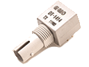
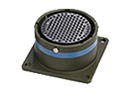
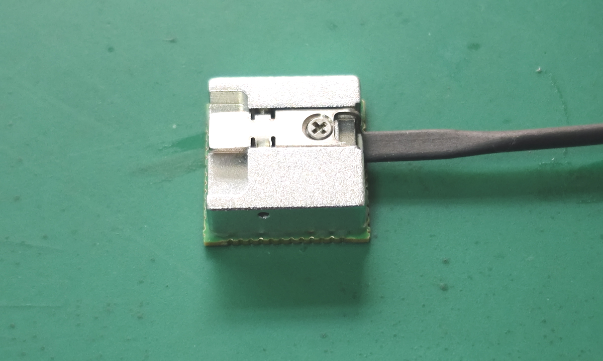
3. After the pigtail is properly secured, tighten the screw in the center of the spring clip to secure it securely. See the figure below.
![1742193247138164[1]](https://gdz.suanmingdashi.com/uploadfile/ueditor/image/202509/1758016048de9a92.jpg "1742193247138164[1]")
Pigtail Fixing Screws Reference Diagram
After the pigtail is assembled, the remaining pigtail length (WL) = L - (4.7 ± 0.5) mm. Refer to the diagram below.
![1742193322117974[1]](https://gdz.suanmingdashi.com/uploadfile/ueditor/image/202509/1758016090babcff.jpg "1742193322117974[1]")
Pigtail Size Reference
Pigtail Length Code Table:
| Pigtail length(mm) | Code | Pigtail length(mm) | Code |
| 30 | 0 | 150 | R |
| 50 | A | 160 | S |
| 55 | B | 170 | T |
| 60 | C | 180 | U |
| 65 | D | 190 | V |
| 70 | E | 200 | 2 |
| 75 | F | 300 | 3 |
| 80 | G | 400 | 4 |
| 85 | H | 500 | 5 |
| 90 | J | 600 | 6 |
| 95 | K | 700 | 7 |
| 100 | 1 | 800 | 8 |
| 110 | M | 900 | 9 |
| 120 | N | 1000 | L |
| 130 | P | 1500 | Z |
| 140 | Q | 定制 | Y |
Note:
For pigtail lengths ≥50mm, flat, round, and loose fiber options are available, with options for springs or guide pins.
For pigtail lengths <50mm, flat fiber options are available without springs.
The standard pigtail length tolerance is ±L*5%.
Special requirements will be discussed separately.