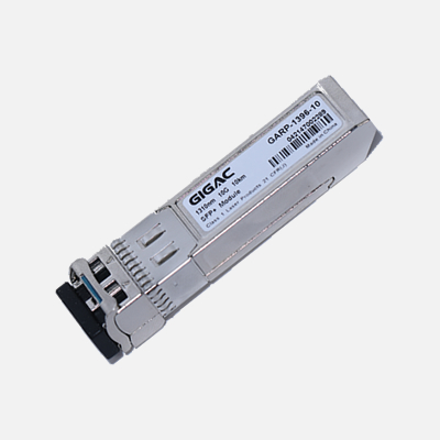
Products Description
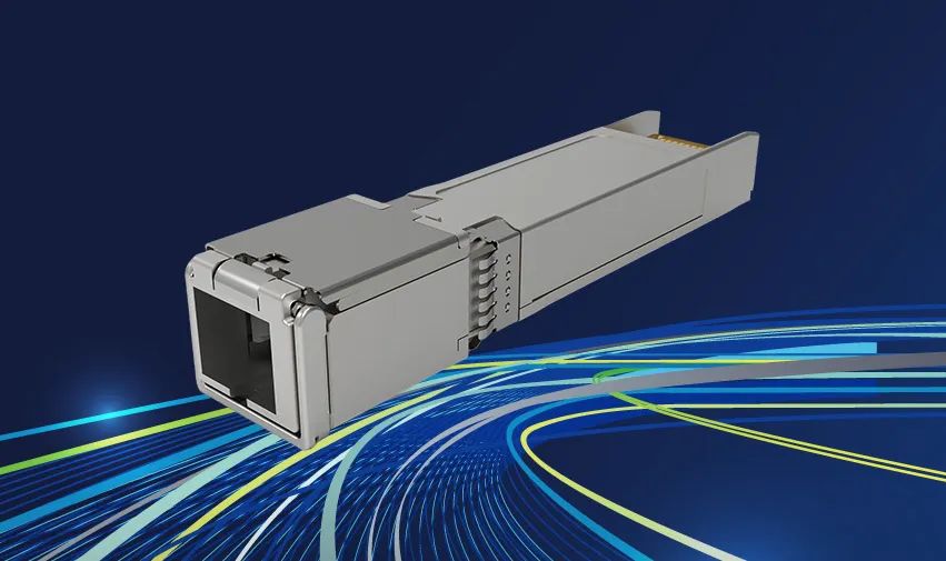
The SFP+ SR module electrical interface is compliant to SFI electrical specifications. Thetransmitter input and receiver output impedance is 100 Ohms differential. Data lines areinternally AC coupled. The module provides differential termination and reduce differential tocommon mode conversion for quality signal termination and low EMI. SFI typically operatesover200 mm of improved FR4 material or up to about 150mmof standard FR4 with one connector.
The transmitter converts 10Gbit/s serial PECL or CML electrical data into serial optical datacompliant with the 10GBASE-SR standard. An open collector compatible Transmit Disable(Tx_Dis) is provided. A logic “1,” or no connection on this pin will disable the laser fromtransmitting. A logic “0” on this pin provides normal operation. The transmitter has aninternal automatic power control loop (APC) to ensure constant optical power output across supplyvoltageand temperature variations. An open collector compatible Transmit Fault (TFault) is provided. TX_Fault is a module output contact that when high, indicates that the module transmitter hasdetected a fault condition related to laser operation or safety. The TX_Fault output contact isanopen drain/collector and shall be pulled up to the Vcc_Host in the host with a resistor intherange4.7-10 kΩ. TX_Disable is a module input contact. When TX_Disable is asserted highor left open,the SFP+ module transmitter output shall be turned off. This contact shall be pulled up toVccTwitha 4.7 kΩ to 10 kΩ resistor
The receiver converts 10Gbit/s serial optical data into serial PECL/CML electrical data. Anopencollector compatible Loss of Signal is provided. Rx_LOS when high indicates an optical signal level below that specified in the relevant standard. The Rx_LOS contact is an open drain/collectoroutput and shall be pulled up to Vcc_Host in the host with a resistor in the range 4.7-10kΩ, or withan active termination. Power supply filtering is recommended for both the transmitter andreceiver.The Rx_LOS signal is intended as a preliminary indication to the system in which the SFP+isinstalled that the received signal strength is below the specified range. Such an indicationtypicallypoints to non-installed cables, broken cables, or a disabled, failing or a powered off transmitter at the far end of the cable。
Features
Optical interface compliant to IEEE 802.3ae 10GBASE-SR
Electrical interface compliant to SFF-8431
Hot Pluggable
Supports rate up to 10.3 Gb/s bit rates
1G/2G/4G/ 8G/10G Fiber Channel applications.
850nm VCSEL transmitter, PIN photo-detector
Maximum link length of 300m on 2000MHz/km MMF
Low power consumption
All-metal housing for superior EMI performance
Advanced firmware allow customer system encryption information to be stored in transceiver
Cost effective SFP+ solution, enables higher port densities and greater bandwidth
For the OBSAI application, the rates are 6.144Gb/s, 3.072 Gb/s, 1.536 Gb/s and 0.768 Gb/s.
For the CPRI application, the rates are 6.144Gb/s, 3.072 Gb/s, 2.4576 Gb/s, 1.2288 Gb/s, 0.6144Gb/s.
RoHS6 compliant (lead free)
Operating case temperature:
Standard : 0 to +70°C
Industrial : -40 to +85°C
Applications
10GBASE-SR at 10.3125Gbps
10GBASE-SW at 9.953Gbps
Other optical links
For the OBSAI application, the rates are 6.144Gb/s, 3.072 Gb/s, 1.536 Gb/s and 0.768 Gb/s.
For the CPRI application, the rates are 6.144Gb/s, 3.072 Gb/s, 2.4576 Gb/s, 1.2288 Gb/s, 0.6144Gb/s. Product description This 850 nm VCSEL 10Gigabit SFP+ transceiver is designed to transmit and receive optical dataover 50/125 μm or 62.5/125 μm multimode
Our factory
Wavelength Divisio···
Detailed Explanati···
The Working Princi···
The Key Difference···
Hot Tags:
R&D laboratory
Gigac has introduced numerous precision testing equipment, such as Ixia XGS12, Ixia WaveTest 93, Anritsu, Fujikura, Fluke, JDSU, Agilent, EXFO, DATA-PIXEL, etc., for product development testing and validation.At present, there are over 100 professional engineers, of which 50% are senior engineers. Through standardized testing processes and in line with international professional testing standards, we provide testing in various aspects such as product appearance, performance, compatibility, and solution scenarios to meet the diverse testing needs of global customers.
Numerous research and development achievements
Gigac adopts a research and development model that combines independent research and joint development, and has achieved outstanding results in industrial design and product software and hardware research and development.As data centers continue to expand and grow, a well planned cabling infrastructure is crucial. Without flexible cabling plans that can easily adapt to common moves, additions, and changes, your network growth will be limited. The Gigac series high-density data center cabling solutions can simplify deployment, enabling up to 144 LC fibers in 1U, and enabling flexible expansion and rapid upgrades with increasing business traffic demands.
Gigac Test Center
Gain a comprehensive understanding of Gigac's optical modules, fiber optic jumpers, and enterprise network testing center. We have a comprehensive testing plan, professional testing equipment, and standard testing procedures. We regularly test optical modules, cables, switches, and other products to ensure that we provide high-quality products to our partners.


