

During the use of optical modules, various problems are inevitable. When we connect optical modules through optical fibers, there may be situations such as the light port lights not working, the light port lights are red, or alarms, optical module failure, etc. Then where is the fault in the optical module? Is it the fault of the transmitting end or the receiving end of the optical module? Is it an internal problem of the optical module itself? Or is it caused by improper external use? This article summarizes common faults in optical modules and provides corresponding solutions to help you detect and troubleshoot faults in optical modules during use.
Common internal faults and solutions of optical modules
In the daily use of optical modules, we may encounter internal faults such as poor optical power, poor eye diagram, poor receiving end, poor operating current, and program programming failure. When encountering the above-mentioned faults, we can check the appearance of the optical module to see if there is any obvious damage, or use some tools to detect and compare it with a good optical module to troubleshoot the optical module fault.
The following content uses a 1G SFP optical module as an example to provide detailed descriptions of the causes of optical module failure, corresponding fault detection methods, and troubleshooting solutions.
Fault 1: Optical module optical power performance degradation
The optical power degradation performance failure of the optical module may cause the following phenomena:
1. The bias current is within the normal range, but the optical power is above/below the control range;
2. No lights are on, the BIAS value is displayed as 0, or the BIAS is short-circuited, and the value is very large, displayed as 90mA-150mA;
3. During the debugging process, some lights are on, but the optical power does not change;
If the first phenomenon occurs in the optical module, it may be due to damage to the TOSA transmission component of the optical module, poor soldering of the TOSA PINs PD+, or a mismatch between the power and resistance and the bias current. The corresponding solutions are: replacing the TOSA transmission component of the optical module, re-soldering and reinforcing the TOSA PINs PD+, or adjusting the power and resistance;
If the second phenomenon described above occurs in an optical module, it may also be due to poor soldering of the TOSA PINs PD+, a faulty memory chip, or damaged beads on the LD- /LD+ lines. The corresponding solutions are: re-soldering and reinforcing the TOSA PINs PD+, replacing the memory chip on the optical module, and reconnecting the same type of beads on the LD- /LD+ lines;
If the third phenomenon occurs in the optical module, it may also be due to damage to the TOSA transmission component or poor soldering of the TOSA PINs LD-. In this case, replacing the TOSA transmission component or re-soldering and reinforcing the TOSA PINs PD+ can be used.
Fault 2: poor eye diagram of optical module
Poor eye diagram of optical modules generally includes poor extinction ratio, eye diagram scattering, irregular graphics, or no eye diagram.
The reasons for poor extinction ratio include too large or too small extinction ratio, in which case the TOSA emission component should be replaced or the optical power resistance should be lowered/raised;
The causes of optical module eye diagram scattering include damaged TOSA, poor performance of the driver chip, or signal impedance mismatch. In this case, the internal TOSA of the optical module should be replaced, the driver chip should be replaced, or the front-end matching resistor should be changed;
When the eye diagram of the optical module shows irregular patterns, it is necessary to modify the values of the pull-up/down resistors and matching resistors;
When the optical module exhibits no eye diagram during testing, it is due to a damaged TOSA or poor soldering of the matching resistor at the front end. In this case, replace the damaged TOSA component or re-solder and reinforce the matching resistor.
Fault 3: poor performance of the receiving end of the optical module
Poor performance of the receiving end of the optical module mainly includes low sensitivity (or even no sensitivity at all) or alarm malfunction.
There are many reasons for low sensitivity or loss of sensitivity in optical modules, such as damaged ROSA components, poor contact between the ROSA pins OUT+ and OUT-, too small extinction ratio of the light source, poor soldering or missing of the magnetic beads, damaged or poor performance of the limiting amplifier chip. For the above reasons, the solutions are: replacing the ROSA component in the optical module, re-welding and reinforcing the ROSA, adjusting the extinction ratio to 10+, re-attaching the magnetic beads, and replacing the limiting amplifier;
When the optical module has an alarm malfunction, the main cause is that the ROSA component is damaged or the alarm resistance is mismatched. At this time, it is only necessary to replace the ROSA component or change the alarm resistance value.
Fault 4: poor operating current performance of the optical module
There are three phenomena of poor operating current performance of optical modules:
1. The open circuit operating current is less than 70mA;
The main reason for the above situation is that the optical module MOS is damaged or the program has not been burned yet. At this time, simply replacing the MOS tube or re-burning the program is sufficient.
2. The working current is greater than 300mA;
When the optical module has the above-mentioned situation, it is necessary to replace the components or observe whether there is any connection between the components due to poor soldering or poor patching.
3. The short-circuit operating current is greater than 500mA;
The main causes of the above situation are short circuits in the TOSA/ROSA or chip, the presence of tin in various components of the PCBA, or short circuits between VCC and GND of the PCBA. In these cases, it is necessary to replace the damaged TOSA/ROSA or chip. If there is still tin in the PCBA components, it is necessary to evenly separate the tin. If the short circuit of the PCBA causes excessive current, the PCBA can only be scrapped and cannot be repaired.
Fault 5: failure in programming the optical module program
There are three main reasons for the failure of optical module program programming:
1. The program cannot be burned;
The main reasons for the above-mentioned phenomena in optical modules are poor performance of MOS transistors or bad patching, poor performance of storage chips or bad patches. In this case, it is necessary to replace and re-attach MOS transistors or storage chips.
2. The program can be burned but without ID;
The main reason for the above-mentioned phenomena in optical modules is the bad or missing placement of the storage chip components. In this case, it is necessary to re-attach the same type of components.
3. Module or shell short circuit;
The module includes TOSA, ROSA, and PCBA, of which only TOSA is metal and connected to the housing. If the optical module has a module or housing short circuit, the TOSA component needs to be replaced and then observed for short circuit. If there is a short circuit, the PCBA or TOSA is damaged and the TOSA needs to be replaced or the PCBA scrapped.
Common external faults and solutions for optical modules
In addition to internal failures of the optical module, external failures of the optical module may also be caused by the operation of the optical module during use, which are mainly manifested in the following four ways:
1. The power light is not on;
This phenomenon is usually caused by power failure, and it is necessary to check the power cord or replace the power supply.
2. The link light does not work;
Check whether the optical fiber line is intact, whether the equipment interface and optical fiber jumper are loose, and whether the optical fiber jumper and coupler are broken;
Check whether the loss of the optical fiber line is too large and exceeds the loss budget of the used transmitting/receiving pair;
Check whether the optical interface is connected correctly, remote local TX and RX connections, and remote local RX and TX connections;
Check whether the fiber jumper is correct, ensure that the connector type matches the device interface (APC/UPC/PC), the fiber type (MMF/SMF) matches the device type, and the supported transmission length matches the link distance.
3. The circuit link light does not work;
Check whether the network cable is a circuit breaker;
Check whether the connection type matches (devices such as computers use cross-over cables, while devices such as switches and hubs use straight cables);
Check whether the transmission rate of the device matches.
4. Severe network packet;
The power port of the transceiver does not match the network device interface or the transmission modes (half-duplex/full-duplex) of the device interfaces on both ends do not match;
RJ-45 head twisting problem;
The problem is caused by an optical fiber connection issue, such as misalignment of optical fiber jumpers or mismatch between the coupler and the jumper.
Optical module installation guide
Avoiding internal failures in optical modules may not be easy, but by following some installation guidelines for optical modules, we can reduce unnecessary failures that may be caused by external factors during the installation process.
Firstly, before installing the optical module, we need to conduct a careful inspection:
1. Check the conductive metal. A good transceiver module should look bright and clean;
2. Check if the packing buckle is intact;
3. Check the port interface of the optical module to ensure that there are no obvious problems inside;
4. Check whether the jumper core is damaged.
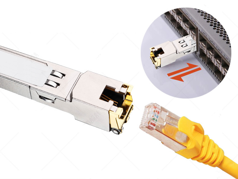
After completing the preliminary inspection to ensure that there are no problems with the relevant equipment and modules, start the installation of the optical module. How do you install and connect the optical module? The following section will continue to explain the installation steps of the optical module.
Step 1: Remove the dust plug from the device slot where the optical module is to be installed; (Tips: If you are not ready to install the optical module immediately, do not remove the dust plug from the device slot, otherwise it may cause contamination of the device port)
Step 2: Insert the optical module horizontally into the device slot. If you hear a "click" sound, the optical module is inserted correctly;
Step 3: Remove the dust cap from the prepared optical fiber jumper and clean the optical fiber ferrule;
Step 4: Remove the dust cap of the optical module;
Step 5: Insert the jumper into the optical module interface;
Step 6: Repeat the above steps for the optical module on the other end of the link. Step 7: Check the port LED status.
Conclusion of the study
When an inserted optical module does not work properly, it may be caused by a faulty optical component or improper installation during the installation process. We should understand the basic information about troubleshooting and testing procedures for optical modules, and take corresponding measures to solve these optical module failures.