


Products Description
Features
Conforming to the GJB599B (MIL-DTL-38999M) I Series Standard, these connectors feature bayonet-type quick connection, with advantages of small size, light weight, and high contact density.
Five-key circumferential identification and positioning, enabling blind mating and preventing mis-insertion.
The outer shell can be constructed from various materials and coatings to adapt to different environmental requirements.
The sockets offer diverse installation options such as box-mounted, wall-mounted, front-mounted, rear-mounted, and nut-secured installations.
The contacts are press-fit and removable, with an anti-skew insertion design.
There are 9 types of shell sizes available, along with multiple pin arrangements.
They exhibit high resistance to vibration.
They possess electromagnetic shielding capabilities.
Key Technical Indicators
Mechanical Properties
Mechanical Life: 500 cycles of insertion and withdrawal
Shock: 3ms half-sine wave with a peak acceleration of 300G
Vibration:
Sinusoidal Vibration: Frequency range 10Hz to 2000Hz, acceleration of 294m/s²
Random Vibration: Frequency range 100Hz to 1000Hz, power spectral density of 1G²/Hz
Environmental Performance
Temperature Range:
Class B: -65°C to +175°C
Class E & F: -65°C to +200°C
Salt Spray: Tested according to GJB1217 Method 1001
Class B: 500 hours
Class E: 500 hours
Class F: 48 hours
Electrical Performance
Dielectric Withstanding Voltage: V
Operating Class | M | N | Ⅰ | Ⅱ |
Sea Level | 1300 | 1000 | 1800 | 2300 |
21000m | 800 | 600 | 1000 | 1000 |
Insulation Resistance:
Under normal conditions: ≥5000MΩ
Under damp conditions: ≥100MΩ
Contact Resistance and Rated Current:
Contact Specification | Operating Diameter mm | Contact Resistance mΩ | Rated Current A |
22D | Φ0.76 | ≤12 | 5 |
20# | Φ1.00 | ≤5 | 7.5 |
16# | Φ1.60 | ≤2.5 | 13 |
12# | Φ2.40 | ≤1.5 | 23 |
10# | Φ3.15 | ≤1.0 | 40 |
Electromagnetic Interference Shielding:
From 100MHz to 1GHz: Minimum attenuation of 85dB
From 1GHz to 10GHz: Minimum attenuation of 50dB
Electrical Continuity Between Shells:
Class B: ≤2.5mΩ
Class E: ≤50mΩ
Class F: ≤1.0mΩ
Other Performance Characteristics:
Relative Humidity: Up to 98% at 40°C
Operating Altitude: ≤30,480m
Excellent resistance to moisture, salt spray, mold, sand, dust, and other environmental factors.
Crimp Contacts
Contact Specification | Pin Diameter mm | Crimping Barrel Inner Diameter mm | Crimping Barrel Outer Diameter mm | Suitable Conductor Cross-Sectional Area mm2 | Suitable American Wire Gauge (AWG) Cable | Suitable Conductor Outer Diameter mm | Extraction Tool Code |
22D | Φ0.76 | Φ0.85 | Φ1.20 | 0.08 0.125 0.2 0.3 | 28 26 24 22 | 0.76~1.37 | M81969/14-01 |
20# | Φ1.00 | Φ1.17 | Φ1.78 | 0.2 0.3 0.5 | 24 22 20 | 1.02~2.11 | M81969/14-10 |
16# | Φ1.60 | Φ1.68 | Φ2.62 | 0.5 0.8 1.0 1.2 | 20 18 16 | 1.65~2.77 | M81969/14-03 |
12# | Φ2.40 | Φ2.49 | Φ3.84 | 2.0 3.0 | 14 12 | 2.46~3.61 | M81969/14-04 |
10# | Φ3.15 | Φ3.40 | Φ4.65 | 4.8 | 10 | 3.42~4.12 | M81969/14-05 |
8# | Φ3.60 | Φ4.55 | Φ6.4 | 8.37 | 8 | 6.4~6.9 | M81969/14-12 |
Solder Contacts
Solder Contact Specification | Solder Cup Inner Diameter | Maximum Suitable Conductor Gauge AWG |
22D | Φ0.9 | 22 |
20# | Φ1.1 | 20 |
16# | Φ1.9 | 16 |
12# | Φ2.9 | 12 |
10# | Φ3.6 | 10 |
8# | Φ4.8 | 8 |
Contact Arrangement (View from the Pin Insertion Surface)

Housing Key Position
Socket Mating Surface

Plug Mating Surface

Key Position Code | 09 | 11 | 13 | 15 | 17 | 19 | 21 | 23 | 25 |
N | 95° | 95° | 95° | 95° | 95° | 95° | 95° | 95° | 95° |
A | 77° | 81° | 75° | 74° | 77° | 77° | 77° | 80° | 80° |
B | - | 67° | 63° | 61° | 65° | 65° | 65° | 69° | 69° |
C | - | 123° | 127° | 129° | 125° | 125° | 125° | 121° | 121° |
D | 113° | 109° | 115° | 116° | 113° | 113° | 113° | 110° | 110° |
Dimensions
JY27467 Plug

Shell Number | A | Thread M UNEF-2A |
09 | 21.7 | 0.4375-28 |
11 | 25.0 | 0.5625-24 |
13 | 28.2 | 0.6875-24 |
15 | 31.3 | 0.8125-20 |
17 | 34.4 | 0.9375-20 |
19 | 37.4 | 1.0625-18 |
21 | 40.5 | 1.1875-18 |
23 | 44.0 | 1.3125-18 |
25 | 46.8 | 1.4375-18 |
JY27466 Wall-mounted Square Panel Front-mounted Socket
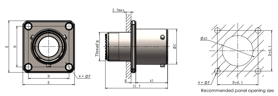
JY27656 Wall-mounted Square Panel Rear-mounted Socket

Shell number | A1 | A2 | B | C | D | E | F | d1 | d2 | Thread M UNEF-2A |
09 | 16.1 | 20.9 | 2.4 | 14.6 | 18.26 | 23.8 | 3.2 | 12.5 | 16.7 | 0.4375-28 |
11 | 16.1 | 20.9 | 2.4 | 17.8 | 20.62 | 26.2 | 3.2 | 15.5 | 20.2 | 0.5625-24 |
13 | 16.1 | 20.9 | 2.4 | 21.6 | 23.02 | 28.6 | 3.2 | 19.5 | 24.5 | 0.6875-24 |
15 | 16.1 | 20.9 | 2.4 | 24.8 | 24.62 | 31.0 | 3.2 | 21.5 | 27.7 | 0.8125-20 |
17 | 16.1 | 20.9 | 2.4 | 28.0 | 26.98 | 33.3 | 3.2 | 25.0 | 30.9 | 0.9375-20 |
19 | 16.1 | 20.9 | 2.4 | 30.7 | 29.36 | 36.5 | 3.2 | 28.0 | 32.9 | 1.0625-18 |
21 | 15.3 | 20.1 | 3.1 | 33.8 | 31.76 | 39.7 | 3.2 | 31.5 | 36.2 | 1.1875-18 |
23 | 15.3 | 20.1 | 3.1 | 37.0 | 34.92 | 42.9 | 3.7 | 34.5 | 39.3 | 1.3125-18 |
25 | 15.3 | 20.1 | 3.1 | 40.2 | 38.10 | 46.0 | 3.7 | 37.5 | 42.5 | 1.4375-18 |
JY27496 JY27505 Box-type square plate socket
JY27496 Front-mounted box-type square plate socket

JY27505 Rear-mounted box-type square plate socket

Housing Number | A1 | A2 | B | C | D | E | F | d1 | d2 | M |
09 | 16.1 | 20.9 | 2.4 | 14.6 | 18.26 | 23.8 | 3.2 | 12.5 | 16.7 | 11.2 |
11 | 16.1 | 20.9 | 2.4 | 17.8 | 20.62 | 26.2 | 3.2 | 15.5 | 20.2 | 14.5 |
13 | 16.1 | 20.9 | 2.4 | 21.6 | 23.02 | 28.6 | 3.2 | 19.5 | 24.5 | 18.0 |
15 | 16.1 | 20.9 | 2.4 | 24.8 | 24.62 | 31.0 | 3.2 | 21.5 | 27.7 | 20.5 |
17 | 16.1 | 20.9 | 2.4 | 28.0 | 26.98 | 33.3 | 3.2 | 25.0 | 30.9 | 23.8 |
19 | 16.1 | 20.9 | 2.4 | 30.7 | 29.36 | 36.5 | 3.2 | 28.0 | 32.9 | 26.5 |
21 | 15.3 | 20.1 | 3.1 | 33.8 | 31.76 | 39.7 | 3.2 | 31.5 | 36.2 | 29.7 |
23 | 15.3 | 20.1 | 3.1 | 37.0 | 34.92 | 42.9 | 3.7 | 34.5 | 39.3 | 32.8 |
25 | 15.3 | 20.1 | 3.1 | 40.2 | 38.10 | 46.0 | 3.7 | 37.5 | 42.5 | 36.0 |
JY27468 Nut-tightened socket

Housing Number | A | B | C | D | E | F | d | Thread M UNEF-2A |
09 | 14.6 | 2.8 | 22.3 | 27.0 | 30.2 | 17.0 | 17.7 | 0.4375-28 |
11 | 17.8 | 2.8 | 25.5 | 31.8 | 35.0 | 19.6 | 21.0 | 0.5625-24 |
13 | 21.6 | 2.8 | 30.2 | 35.0 | 38.1 | 24.3 | 25.6 | 0.6875-24 |
15 | 24.8 | 2.8 | 33.4 | 38.1 | 41.3 | 27.6 | 28.8 | 0.8125-20 |
17 | 28.0 | 2.8 | 36.6 | 41.3 | 44.5 | 30.7 | 32.0 | 0.9375-20 |
19 | 30.7 | 3.6 | 39.7 | 46.0 | 49.3 | 33.9 | 35.2 | 1.0625-18 |
21 | 33.8 | 3.6 | 42.9 | 49.2 | 52.4 | 37.1 | 38.3 | 1.1875-18 |
23 | 37.0 | 3.6 | 46.1 | 52.4 | 55.6 | 40.0 | 41.5 | 1.3125-18 |
25 | 40.2 | 3.6 | 50.8 | 55.6 | 58.8 | 43.4 | 44.7 | 1.4375-18 |
J599I Series Printed Circuit Board Socket
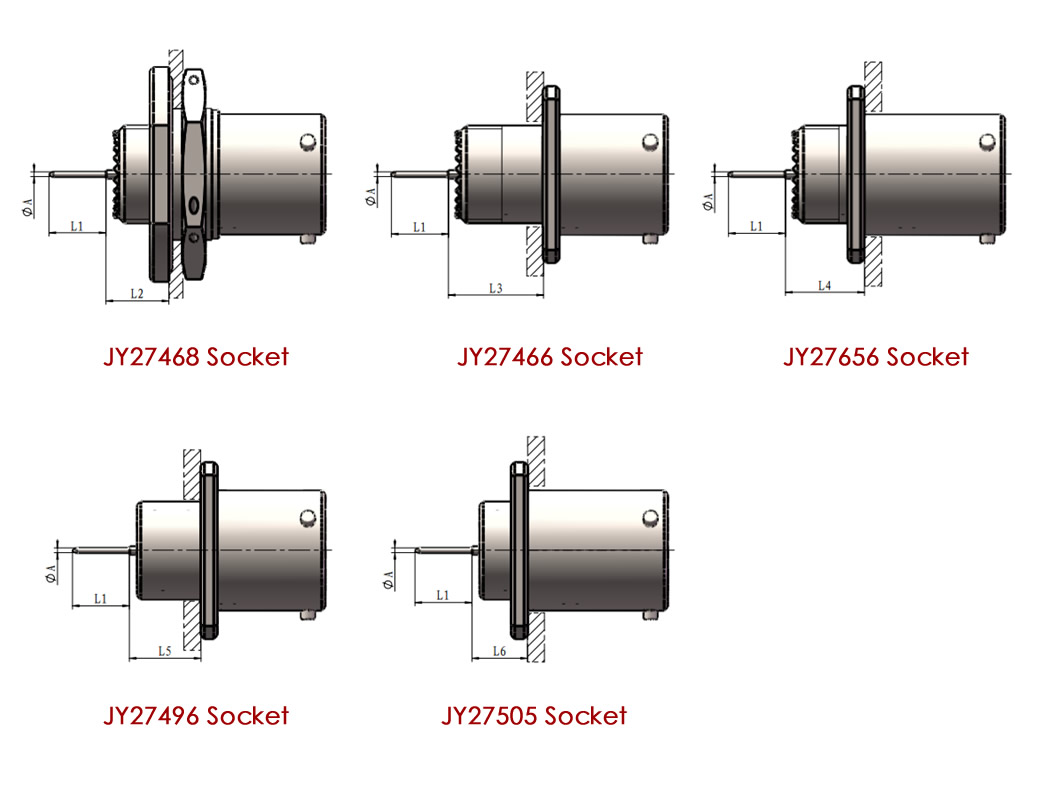
Specifications of printed board contacts | L1 | A | |
22D | long printed board contacts | 8.5 | 0.7 |
short printed board contacts | 4.0 | ||
20# | long printed board contacts | 8.5 | 0.7 |
short printed board contacts | 5.0 | ||
16# | long printed board contacts | 8.5 | 1.15 |
short printed board contacts | 5.0 | ||
Size | Housing Number 09~19 | Housing Number 21~25 | ||||
Fitted with 22D pins | Fitted with 22D sockets | fitted with 16# or 20# pins and sockets | Fitted with 22D pins | Fitted with 22D sockets | fitted with 16# or 20# pins and sockets | |
L2 | 9.06~10.06 | 8.74~10.06 | 9.24~10.23 | 9.06~10.06 | 8.74~10.06 | 9.24~10.23 |
L3 | 13.91~15.08 | 13.58~15.08 | 14.08~15.25 | 13.91~15.08 | 13.58~15.08 | 14.08~15.25 |
L4 | 11.60~12.47 | 11.27~12.47 | 11.77~12.64 | 12.35~13.22 | 12.02~13.22 | 12.52~13.39 |
L5 | 9.91~11.08 | 9.58~11.08 | 10.08~11.25 | 9.91~11.08 | 9.58~11.08 | 10.08~11.25 |
L6 | 7.60~8.47 | 7.27~8.47 | 7.77~8.64 | 8.35~9.22 | 8.02~9.22 | 8.52~9.39 |
Overall dimensions of J599I series welded products

Specifications of welded contacts | L | inner diameter of welding cup | maximum suitable wire gauge(AWG) |
22D | 4 | Φ0.9 | 22 |
20# | 4 | Φ1.1 | 20 |
16# | 4 | Φ1.9 | 16 |
12# | 4 | Φ2.9 | 12 |
10# | 6 | Φ3.6 | 10 |
8# | 6 | Φ4.8 | 8 |
Our factory

The Evolution and ···
 and combiner unit (OMU)")
Wavelength Divisio···

Detailed Explanati···

The Working Princi···
Hot Tags:
R&D laboratory
Gigac has introduced numerous precision testing equipment, such as Ixia XGS12, Ixia WaveTest 93, Anritsu, Fujikura, Fluke, JDSU, Agilent, EXFO, DATA-PIXEL, etc., for product development testing and validation.At present, there are over 100 professional engineers, of which 50% are senior engineers. Through standardized testing processes and in line with international professional testing standards, we provide testing in various aspects such as product appearance, performance, compatibility, and solution scenarios to meet the diverse testing needs of global customers.
Numerous research and development achievements
Gigac adopts a research and development model that combines independent research and joint development, and has achieved outstanding results in industrial design and product software and hardware research and development.As data centers continue to expand and grow, a well planned cabling infrastructure is crucial. Without flexible cabling plans that can easily adapt to common moves, additions, and changes, your network growth will be limited. The Gigac series high-density data center cabling solutions can simplify deployment, enabling up to 144 LC fibers in 1U, and enabling flexible expansion and rapid upgrades with increasing business traffic demands.
Gigac Test Center
Gain a comprehensive understanding of Gigac's optical modules, fiber optic jumpers, and enterprise network testing center. We have a comprehensive testing plan, professional testing equipment, and standard testing procedures. We regularly test optical modules, cables, switches, and other products to ensure that we provide high-quality products to our partners.